Wednesday, October 10, 2012

Solid Lumber Sheathing

Recent Photos:
We opted for solid lumber sheathing, right from design.  It is a fairly vapour-open sheathing, due in large part to the gaps, which is what we wanted.  It is also strong - allowing us to apply a wide variety of finishes, and place strapping anywhere we want.  The lumber used was good one side 1x10 (22 x 235mm) pine/spruce, gotten for a really good price.  It was actually 7/8" (22mm) thick.

Basement window install.  The peel and stick flashing on the bottom covers shaped rigid foam.  It will be covered with a metal flashing as well.  There is a good 1" space between the window and the concrete, which was formed to overlap the window on 3 sides.  The window sits in a 3/4" (19mm) plywood box cantilevered out from the inner wood frame, but is supported by the rigid foam at the concrete.
Note the concrete drip edge cast into the window opening.


Sunday, September 9, 2012

Sunday, July 15, 2012

Rainwater Harvesting With Solar PV Panels

A Marriage Made in Heaven!

As the project progresses, we've been blessed with making connections with some excellent contributors:

I've mentioned some of them before, but most recently we've been connected to DTE Solar as well as Boss Solar, and Trevor at EcoInsulation, Reiner (the Reno Coach) all excellent people.

One connection was with John Paul from DTE Solar, who has put me onto rainwater collection as an energy-related component of our project.  He's written an excellent article on the topic, discussing rainwater collection's potential impact on the City of Toronto's energy, waste, environmental and financial costs.  It certainly opened my eyes to the amazing, yet highly under-appreciated costs of water treatment, distribution to and from, etc.  These are costs easily offset by rainwater collection if implemented ubiquitously.  Not to mention water costs in Toronto have increased about 8% per year for some time now.

After some discussion we've together arrived at tantalizing possibilities for our own project.  The fact that PV panels are glass-clad means they present a premium surface for rainwater collection.  The trouble is that they are not designed for this task - which I certainly feel they should be.  In fact, I would like to see PV panels made as large interlinking panels that shed water - This way they can be installed on the roof without plywood (so using PV panels, one eliminates not only the shingles but also the plywood layer, although the roof shape must be planned with this in mind), perhaps directly to the rafters or purlins.  The benefit is they can be wired or accessed from the backside (from inside the attic), they can serve as the roof, and shedding water all the way down the roof, rainwater collection becomes a breeze - not to mention the quality of the collected water is also improved.  In any case, given the current, less-perfect situation of panels on rails on shingle roof, JP's thought was to add troughs underneath the panel gaps to collect the water - in our case 3 long troughs, and direct it to the collection reservoir.  However, what if we also introduced pipes onto the roof to pump that rainwater from the holding tank onto the solar panels?  I believe by dousing the panels with rainwater we can cool them dramatically, increasing electricity yields significantly - perhaps as much as 10%, even after pumping losses.  Some of the water will evaporate, but much of it will just flow back into the collection system, where the heat may again be made use of - a heat pump can take the heat from the rainwater collection tank and port it to the DHW (domestic hot water) system.  Even if not, an un-insulated rainwater tank in the ground is constantly being cooled by the soil, so that over the hot summer season, there will be a significant cooling capacity available for the solar panels.  This cooling action will also lengthen the lifespan of the solar panels.
This is in a way similar to the new techniques appearing whereby the heat from the solar panels is being captured by flowing air over/under the panel backsides.  The heated air is then used in the building.  I've read this can increase by some 90% the energy harvested via electricity alone.  But air is generally a lesser medium than water - which is compact and easily filtered and transported in pipes.  Air carries dust, and requires larger ducts to move it.  And the fact that it is a (compressible) gas means there are a lot more losses related to its handling (pumping).
Mike at Boss Solar has devised a water coil to attach to the backs of solar PV panels to both cool them and capture their heat - but this seems a lot more difficult and costly than the 'rainwater collection' idea, - which appears to be - a marriage made in heaven!
Notice how there are no photos or sketches here.  The ideas are very simple.  This seems to be the reality of rainwater collection as it is with other aspects of super energy efficient houses - not glamorous - just important.


Sunday, May 27, 2012

Roof and Solar Install

The active period continues and just last week we completed our solar installation immediately after the roof install.  The photo shows the Schuco racking in place and the first day of panel installation is nearly over.  The racking took one day to install, with the 45 250W poly panels an additional two days.  Roof pitch is 8/12 - walkable, but not that comfortable.

Notes:
Schuco rails are heavy duty.  We received our rails from our supplier DTE Solar's old stock.  This was fortunate since the rails were a full 20' long.  The new products out there are apparently available in standard 10' lengths only.  Longer lengths are special order.  I was glad we were able to get these longer lengths.  The L brackets, which are attached to the roof throuth the shingles and into the rafters with 1/4" x 3.5" stainless lag screws are mounted along each rail, 4' OC.  Pre-drilled mounting, with a special flashing that tucks under the shingles and sealant is applied under the brackets as well.  This is a long and messy job - the mounting of all these brackets.  It is also very permanent.  Once in place, it becomes an issue to repair the roof under these feet.  And all the traffic on the roof in warm weather has really worn down the shingles.  Especially near the scaffold.  However, we are expecting the shingles will last a long time due to their being protected a great deal by the panels.

Note:  We originally intended to go with a standing seam metal roof.  Price for our Vicwest Tradition 100 22ga painted steel roof was $7.50/SF (this is a very thick sheet metal gauge for steel roofs), compared with $2.30/SF for the shingles (including full Ice and water on the south side and ridge vent).  Major difference in cost, but we were totally willing.  It would have been an excellent looking roof, but also extremely long lasting, recyclable, good for rainwater collection (no much concern of the tar from shingles), and waterproof.  In addition, the solar panels would have been mounted directly to the steel seams with S-5! clamp mounts, giving a very sleek and low-profile integrated panel install.  Unfortunately, the timing didn't work out and we had to meet our microFIT deadline, so we went with a shingle roof (not to mention we are elated at the cost savings).

HOWEVER:  One thing to keep in mind:  The metal roof with the S-5! mounting would have been a very versatile roof/solar system, because the S-5! clamps can mount anywhere along the seams, and there are no penetrations through the roof.  The rail system is quite a downgrade (although significantly more expensive than the S-5!) in my view because once those rails are in place, they are not moving.  Whatever the future brings, it must go on those rails.  And one thing I'd like to see in the future is that we increase the number of panels on the roof - no chance with those rails - with the S-5!, it would have been simpler, I think.  I do foresee that people will want solar PV even beyond the microFIT limits.  I certainly do - the cost is so reasonable right now, and I feel it can be made even cheaper by not using the inverters - for example solar PV water heating can do fine with DC - no need for AC.

The panels are on a portrait layout, 3 rows of 15 panels for a total of 45.  6 Rails, 2 for each row of panels.  The rails have a splicing hardware which is basically a bar that slides into the rail grooves and screws in place.  Note, with the metal roof and S-5! clamps, it would have been a landscape layout. We have two 5kW 'Power One' inverters for a total output of 10kW.  The array is rated at 250x45 panels for total of 11,250W.  One is allowed to install up to 12kW for a 10kW system capacity.  We could add 3 panels to the system - perhaps on the garage in back?  Each inverter takes 2 channels of DC input.  We have therefore divided the array into 4 blocks - 3 with 11 panels and one with 12 panels.  This uneven-ness is no problem for the inverters to handle (without any loss of energy to speak of).

What is annoying to me is the system architecture mandated by the MicroFIT program.  It centres around this Anti-Islanding feature.  Simply, the system is not configured (and cannot be configured, I'm told) to provide the homeowner directly with power, bypassing the grid.  In other words, the array serves the grid only, and the inverters shut off automatically if they detect no grid.  This means they cannot be used to provide the household with power.  Personally I hate this - it means there is no redundancy benefit for the owner.  When the grid is down (during a blackout), so is our own generation system.  This serves to protect hydro workers from being exposed to electricity while they repair the grid.  Investigation is needed to see if there is a safe and legitimate way around this.


Saturday, May 12, 2012

Ext Frames, Roof, and Solar Installation

We've had a very active recent month.  There was a tour from the recent Passive House training held in Toronto.
We've received gifts-in-kind from Terrell Wong at Stone's Throw, 3C Carpentry (Carlo Terzi), Jimenez Carpentry, and friendly support from neighbours.  Of course, Fourth Pig Workers Co-Op have provided excellent carpentry services throughout.  We've also had strong support from our metal roofer Heritage Tinsmiths, who waived a significant cancellation fee when we ran into some timing and other issues.
And we've had another volunteer added to our list of observers and helpers.
PV Master and DTE Solar have been excellent as well. - Plugs for you all!


Our solar PV installation is shaping up.  One of the issues was the load side electrical service which must be in place first.  We really wanted to avoid an ugly overhead service to the building (where birds sit and poop on cars), and the balcony on the south-w corner made it even worse (electrical lines must stay well clear of openable windows and balconies).  It also results in these plastic conduits running all over your side facade.  We'd been working with Toronto Hydro since quite a long time ago to get an underground service to the building - but costs and timing were major issues.  They request $1000 to make a drawing, plus $6000 to $12,000 for the actual work, and 3 months lead time.  Like everyone else, we ended up having no time or money for this, so we placed our own hydro pole at the corner of our property and made our own underground service to our own pole.  From there it is a short 15' overhead run to the city's pole.  One of the design considerations with utility rooms is the following:  On a corner house in the city, you often will have additional choice as to which side of the property the service comes from, as in our case.  With the new smart meters, the electric company is less concerned with mounting the meters close to the front of the house - although it is still preferred.  Mid-span connections are also possible - so there was ample choice for us.  I found out it is even possible to have the main service attached to our detached garage - and have the house fed from the garage rather than vice versa.  However, getting the service to the electrical panel was tricky because we wanted the electrical/utility room on the north side (back of the house), since it is a room without windows - this location was the furthest from the possible meter locations.  During the concrete wall stage, we placed a 2" conduit in the ground around the building  from the electrical room to the anticipated meter location - a run of about 50'.  Later, we dug up the ends of this conduit and routed it into/onto the building exactly where the meter and panels would be.  Connection costs to the city for electricity are minimal (currently the standard price for a permanent connection is $850).  We paid $1500 for the pole installed, and another $1300 to run the service to the pole, including trenching, conduit, wire, weatherhead, etc.)  While I'm not thrilled to see another pole in the neighbourhood, I do hope that one day, I can work with hydro to extend our underground service right up to their pole and do away with ours.

Hydro Pole Installation:  You need to hire a company with this special truck designed for installing hydro poles.  In our case, York Power and Lighting.  Note the pole length.  This was a standard pole of 30'.  We needed only about 17.5' out of the ground, so we chopped off 7.5'.  burial depth is 5' for this small pole.  4' is ok as well, but I elected for 5'.  This was a good thing because the trench up to it stayed open overnight in quite windy weather - I was glad the pole didn't fall down.  Minimum height is 16', per Toronto Hydro specs.  
Lifting up the tall exterior frames.  This is 2x8, 16" OC with two rows of blocking and diagonal strapping on the backside.  Not quite meeting the tall wall specs in the code, but OK, since it will be thoroughly braced to the 2nd floor assembly when we get the scaffolding up.  Lifting it was a piece of cake with a chain fall/lever hoist anchored to a large beam in the cathedral ceiling assy.  With the other walls, there was a lack of large beams to anchor to, so we connected to the 1/2" anchor bolts in the concrete wall on the far side of the building.
Note the tilted blocking.  This is 2x10 blocking material in a 2x8 stud frame.  Tiled to ease the installation of the cellulose later on. I would have liked it if we thought of this earlier - the tall walls around the stair could have benefitted from this idea.  You can see the temporary frame we set up on the ground to build the next wall.  That was the longest wall we built and lifted in one piece - approx. 2000lbs, and 38' x 20'tall.  Two hoists were employed.  Worked fine.

Tall walls and rafter beams in place.


South side rafters going in.  These double 2x6 rafters turned out to be a fair bit of labour.  The building is overbuilt in some areas, but I'm happy about not skimping on the frame and concrete.  We do plan to economize in other areas - but not in these.  With our overbuilt frame, I feel confident our structure will do better in this time of climate change - who knows how much snow will fall next winter, or how heavy future solar equipment may become?  The historical design snow load in North York is about 1.2kPa, but only 30km to the north, it increases dramatically.  The rafters are placed at 16 1/16" on centre, and carefully laid out so the pattern is centered on the building.  This was to accept the standing seam metal roof (another story), and so that the standing seams would line up exactly with the 3" thick rafters.  Thus, the seam pattern on the roof would also be centred on the building.  Don from Heritage Tinsmith told us the standing seam panels end up being a little over 16" on centre.  All this will allow the solar panel installation to be very strong and secure.  It will be easy to keep the 5/8" T&G roof plywood in line with the rafters - we'll just provide a 3/8" gap between panels to compensate.  The fact we are using 3" thick rafters means it will be easy to install the plywood regardless.
Lots of rain in recent days, making the whole place a mud-bath - mainly because of all the grading and trenching going on.  Tip:  trenching in winter can be cleaner due to less rain.  The problem is the mud is carried right through the building at this stage since we are working on the roof.  Note the black sealant we've applied to the attic floor seams.  It is Bakor Aquabloc.  Very effective, but messy for the first day since it is water soluble until cured - and it rained just an hour after we trowelled it on.  The black stuff flowed and got deposited as a residue in other parts of the building.
Sewer and water service also connected and you can see the new bit of fence we had to put up once the hedges were mowed down during the installation.  This was OK, however, because we planned it that way.....there will be a short walk through the hedge in this area, to the east entrance.  The sewer service is a single 6" PVC pipe with 6" clean-out.  The pipe is reduced to 4" before it goes into our building through the 4" pipe we installed during the footing pour.  We should have installed a sleeve for the water service as well, because they had to dig under the footing to place that in any case.  You would think they could have used something like a 2" earth auger to drill through the earth - but they dug it - messier.  The city's contractor did this work - they charge about $7500 to do a sewer connection, and about $3000 for a water service.  We elected to re-use our existing 3/4" water service, but still had to pay some $400 so they could inspect it.  The sewer pipe is simply left open for all the sewer gases to enter the building - we've since plugged it.  Wondering if we can get rid of our portable toilet soon, which costs about $175/mo in winter, and a bit less in summer.


Wednesday, April 11, 2012

Exterior Renderings

Here are some recent renderings from work we've been doing on the exterior design.

Sunday, April 8, 2012

Framing Photos

Tall Walls

2x12 Platform supported on the elevator shaft and one slanted upright from the concrete.
North Facade, Temporary Stair.

South Facade.


Fir beams were a last minute addition.  It caused some level of delay, especially when I realized I needed them slightly stronger.  I decided to place them doubled at 24" OC, and I had to order an additional 7 after the first ones arrived (Montreal supplier).  They are solid fir, dressed 4 sides, 2.5" x 9.25", $4.90/ft.  Our gluing job was not very successful and thus the C-clamps holding many of them.  More clamps are needed.  This is a great way to 'improve' headroom without having a change in floor heights upstairs, and without incurring additional exterior wall areas to be made (which is the usual result of taller ceilings in houses).  Our ceilings on the main floor are 9' to bottom of joists.  One-side-good special fir plywood was placed atop the beams.  The beams are placed carefully so as to be directly underneath the closet walls upstairs.  So no blocking is required under those walls, and nails will go directly into the joists.  We were careful to use galvanized nails on the joists to avoid rust stains.  When the last 7 beams arrived, this was forgotten and some rust stains have now appeared on the affected members - so far very minor.  We will see how much sound attenuation is needed over this area.  If a lot, we may need to add a sound absorbing medium to the floor upstairs.  This possibility was addressed by building all the door openings 3" taller upstairs, anticipating possibly a gypcrete pour on the floor, and sono-base panels under the finish flooring.

Cast in Place Electrical Outlets

Our search for cast-in-place electrical outlet boxes for the exteriors of the concrete basement walls ended without result.  We've probably all seen those grey PVC or painted aluminum outdoor boxes mounted on the surface of the basement walls.  Ugly.  Oddly enough, there is very little out there to address this issue.  I did find one product by IPX called Kwik-On.  Normally, electricians use 'slab boxes'.  These are similar to the metal boxes used for surface-mounted outlets.  They have no way to secure them to the concrete forms (odd, but true) - I believe the EMT conduit is intended to keep them in place while the concrete is poured.  They are not designed for exterior use, or for walls, and the electrician tapes them all ove to keep the concrete out.  There is also product in Europe where they tie the box to rebar and then cast around it.  The opening is knocked out later.  Availability and cost led us to design our own solution - which was relatively cheap - Materials for each box cost about $7.  Quite good, I would say.

It was just a simple outdoor PVC box mounted to an oiled wooden plate screwed to the box face.  PVC conduit was affixed to the back of the boxes so they could carry wire into into the building from the box.  The wooden plate was delicately mounted to the concrete forms with small nails.  Note:  make the total length a good 1/4" or more shorter than the thickness of your concrete walls - our forms were not well cleaned and the concrete scale on their inside surfaces sometimes interfered with the delicate boxes.  Also, be sure to carefully and thoroughly move the concrete around the boxes to ensure the concrete does not honeycomb around them.

Here are some photos of the process.


The conduit ends in a threaded coupler, sealed with tape for later removal.  Be sure to taper all sides of the wood plate well.  We tapered only the tops and bottoms and found removal after casting could have been a little better with all sides given a decent draft.
The depth and breadth of the depression left by the wood plate is large enough to accommodate the thick, hinged weather-proof PVC cover that will go on this.  Note, we may still apply another finish to the concrete - not likely stne veneer - possibly stucco, hopefully shot-blasting and staining the concrete.

Elevator in a Passive House

Here is our main floor layout:
Why would anyone install an elevator shaft in their house?  Can't people just climb the stairs? - its better for them.  We completely agree.  And if you'v ever used a residential elevator, you'll find it much slower than the stair.
However, there are some compelling reasons to consider the elevator shaft - note the key word - shaft.  We are not installing an elevator - but we are installing the shaft, which turns out to be quite cheap, even with us doing it the expensive way (more on that below).  Here is our thinking:
  1. We've seen seniors close to us living with their grown children.  It is really hard for them to go up and down the stairs.  We want a house which is inviting to our parents.  We've placed a bedroom and full bath on the main floor - but there are still stairs to climb to get to the first floor from the outside.  The elevator facilitates at-grade entry into the building.  It also allows the grandparents to easily visit their grandchildren asleep in their beds upstairs, or to join the family in the den for a movie, etc.
  2. Sometimes a family member is in a wheelchair.  The elevator embraces this.  Not to mention, any one of us can become a wheelchair user overnight. A house ready for an elevator is one less problem during a traumatic life-changing event.
  3. The elevator can make moving heavy or large objects much simpler - like pianos.
  4. Space lost to the elevator is not lost unless the elevator is installed.  The empty shaft (with floors installed on each level) can serve as pantry, powder room (with plumbing), closet, rock-climbing wall (no floors), etc.  We plan to use the shaft in these ways, until an elevator is actually installed.
Intended for economical installation, the shafts for residential elevators are intended to be built using regular framing lumber, with studs spaced extra-close and thicker plywood sheathing, or the use of 2x12's on the flat, flanked by studs within the wall framing.  Exact details are per the elevator manufacturer.  What is not explicitly laid out is that these walls are intended to be of standard height, framed between floors.  The idea is to place the elevator shaft in an area where there is a floor all around it, on all levels.  This did not happen in our design.  As our goal was to make the building accessible from the outside, we needed the shaft to be located near an exterior wall, and we ended up placing the shaft inside a wrap-around stair (the stair is placed on the north corner of the building - see plan).  Thus, a person entering the building from the north door arrives on the stair landing, from which he can enter the elevator.

The shaft walls needed to be about 28' tall.  This height is an added expense to frame, and if executed in wood, would take up a lot more space (tall wood walls tend to use deep studs too).  We therefore made a steel frame - cost of the steel - about $6000 incl delivery.  Concrete pad - $1000 labour and materials.  Crane - $600 minimum charge).
In addition the walls around the stair became very tall - from the footings to the ceiling of the 2nd floor.  28' long 1.75" x 9.5" LVL's (engineered lumber) were brought in to handle this, 12" OC, with double king studs.  The LVL's were about $4.90/ft - as costly as steel! 

Here is a video of the shaft going into the building on March 20, 2012.

...and some images;
The steel shaft arrives right on time from Ontario Steel with all the necessary certifications in a folder.  Our guys get on the truck and measure everything before we offload.  We are very pleased with their work.  Straight and square, and with good welds.  The piece is all 3.5"x3.5"x1/4" thick structural steel tube, and the finished weight is only about 2500 lb.

The crane operator removes the shaft from the truck.  We re-rig it on the driveway and then stand it up and into position.
The shaft in its home.

Look closely to see the 1/16" HDPE plastic gasket under the 1/2" steel plate foot.  Holes in the plates are 5/8".  Steel shims prepared ahead are ready for use.  Standard 1/2" x 8" HD galvanised  anchors are holding the frame to the 30MPa concrete pad with 10M reinforcement at 12"OC both directions.  The pad is about 10" thick - over strong, really.  The bottom of the shaft was prepainted with a finish coat of enamel.  The upper parts were only primed as we intend to weld to it.


You can see the 3" thick high-strength (60psi) rigid XPS foam insulation under the pad.  This material was about $70 for a 2'x8' sheet.

The bolt positioning jig is simply 3/4" plywood raised 1.5" from the concrete. You need to work the bolts well so there are no depressions in the finished concrete around the bolts.

Originally designed to be inside the elevator pit, the sump pit was installed to the side due to concerns about a clause in the elevator code requiring the the pit to stay dry.  We have both exterior and interior weeping tiles, and a very deep and large sump pit to accommodate 2 pumps.  

So how does Passive House deal with the elevator shaft? - I've had no official answer on this question, but assume it will be treated the same as a stair case - Total Floor Area of the elevator and shaft is not counted.  However, since we are installing only the shaft, we are expecting to have the area on three levels included in our PHPP.
I've also yet to ascertain the energy requirements of the elevator over the course of a year.  Again, we will be avoiding this issue (w.r.t. to PH certification) by not installing the elevator.

Saturday, March 10, 2012

All the Framing is Backwards!

We've had people go by our site and wonder why we were doing things backwards.  Normally, one builds the concrete walls and places a wood floor system on top of it.  We didn't.

The wooden house frame rests on the footings - not on the concrete walls.  Why?  One thing we're discovering about radically energy efficient buildings is the structure!

When the structure is not designed for insulation, it gets very hard to achieve thermal-bridge-free construction.  Placing the first wood (or steel, or whatever) floor frames on top of the concrete walls means there is a strong connection to the concrete (a heat conductor, not an insulator).  Unless the concrete is on the warm side of insulation, this is a significant thermal issue.  In our design, the structural concrete is all on the cold side of insulation.  (This means the outside shell of the building is hard.  When one thinks about a building lasting 25 years, having rigid foam on the outside might seem OK.  But what if we want  it to last 150 years or more?  Well, I don't know if that will happen with this house, but in case it does, it seems a good idea to have the outside shell be hard and durable.  One loses some potential to have thermal mass inside, but that can be achieved in other ways).  Getting back to the wood frame, we therefore have thermal separation between the inner frame of the house (which is the structural frame) all the way from the footings, up to the roof.  Therefore, framing starts in the basement, not on top of the concrete walls.  This might seem like a radical departure from conventional practice. But so far, in our project, we've found no real problem, and we are framing the 2nd floor walls now.


There are some considerations to handle, however.  First, we start with wooden walls, not floors.  The reason for this is that if we started with floors, the insulations inside them would get all wet.  So we wait for the roof to be on and the building closed up before building the basement floors.  This also reduces the natural settling of the building - pretty much all of the shrinkage of framing lumber happens in the floor frames.  Although we built the wide footings very level, we also shimmed the walls so they are not in contact with the concrete and any water can drain from under the walls, into the space between the footings, and finally to the sump pit.  

The walls against the concrete are not sheathed.  Again, this is so we can insulate the space behind the frames after the building is closed in.  We borrow shear strength from the concrete walls to stabilize these open frames.  The photo below shows a wide 3/4" plywood top plate (placed over the upper top plate) which reaches to the concrete and laterally anchors the walls to the concrete with steel brackets.  The 1/2" female Zamac anchors ($1 ea) were placed in the forms during the wall pour, but could probably be drilled in afterwards.  The concrete crew didn't really pay attention to the location of these anchors so you'll see that some of the steel brackets connect to the underside of the plywood, and some to the upper side.

Tuesday, January 31, 2012

Smallest Wood Stove and Smallest Wood Boiler

Adding some new information:
Yeaaaah!  We've found the whole load of stuff.  To find small boilers, look in the UK and Europe also, but lots of people use wood stoves in the UK, and they frequently have small houses, so there are lots of small wood stoves, and small wood stoves with what they call back boilers.
Charnwood has a distributor in NA, and their Cove 2B model could be a good size for low energy homes.
The following site lists quite a few different wood stoves with back boilers, some fairly small:

www.stovesonline.co.uk/stoves_with_backboilers.html
Also see:
www.boilerstoves.co.uk

And if you are looking for really quite a small output, the Salamander Hobbit below now has a back-boiler option (!).
Salamander is now also offering their Hobbit stove in a DEFRA -approved version and they have an even smaller stove called the Pipsqueak.


I have been getting more and more interested in the possibilities of wood stoves and wood boilers - BUT cannot find that very small, high-efficiency, sealed-combustion, direct-vent wood boiler!  This would be ideal for the occasional back-up hot water heating, and possibly snow-melting.  However, I have located a number of smallest wood stoves, some of which are beautiful!

Here are some:
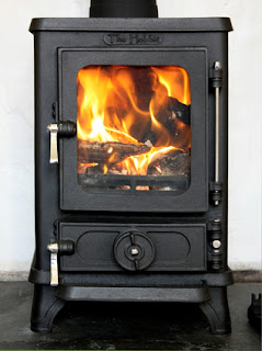
http://www.salamanderstoves.com/docs/64/the_hobbit/  4kW output (14,000BTUh), $800 including delivery to NA.


The link below is really a very sweet little stove - The Thelin Gnome - it is a 16" diameter pellet stove.  Really Compact, but about $3000, I hear.
The search I do to find these things is now evolved to be 'Sailboat wood boiler', and 'micro wood boiler' and 'micro wood gasifier'. 

Here is a very cool stove for an RV or a Sailboat - made of stainless:  The Kimberly Stove:
It is about $3500, I think.

The Jotul 602 is about $1200 in the Toronto Area.
The F602 is listed at 28,000 BTU output - about 8kW - 19x11x25"h cast iron, non-catalytic clean burn 75% efficiency.  Uses room air for combustion.  Apparently there are really no direct vented wood stoves - I don't understand why.
I'm discovering there are a lot of these in the UK:
Here is the Acorn by Aarow, 4kw (about 14,000Btuh), and priced at 658 pounds.


8kW Wood Boiler available in the UK for 599 pounds.

Another one from the UK, this one priced at 539 pounds.


30,000 BTUh, 17x14x28"h including legs


http://www.marinestove.com/herringinfo.htm  This site lists three or four tiny wood stoves for sailboats.  Lovely.

http://www.waldeneffect.org/blog/Smallest_wood_stoves/

http://www.youtube.com/watch?v=xDUrSsILmNA&feature=related

http://www.fatscostoves.com/

http://www.theboilerwerks.com/

http://www.refleks-olieovne.dk/

http://www.blakes-lavac-taylors.co.uk/prod01.htm - Kerosene, Diesel, and Parafin heaters

A very small, 55,000 BTUh on-demand propane water heater:
http://www.globaltowne.com/product_info.php/products_id/54

An Excellent resource on heating with wood, its history and all the different types of wood burning appliances.
http://autonopedia.org/crafts_and_technology/Woodburners/Wood_Stoves_Part1.html

Ah!  Found a water heater for a jacuzzi - the CHOFU!
http://www.islandhottub.com/woodhtr.html - about $1200 from Amazon.com right now.

To convert any woodstove into a water heater:
http://www.hilkoil.com/  By the way, as far as I can tell, there are wood boiler makers using these coils such as this one:  http://nationalstoveworks.com/hotwaterstoves.html

An engineer who's built his own wood-fired cookstove/space heater/water heater.
http://www.gulland.ca/homenergy/stove.htm

Wednesday, January 25, 2012

Construction Has Begun

So much to report!

We started construction.  There's been about 2.5 months in prep, but just three weeks with crews on site -
Starting Tuesday Jan 10th:

Prep:
Moving out, finalizing drawings (ongoing!), disconnecting electricity, gas, water, phone, etc. Salvaging all we could form the old bungalow, sourcing specialty materials, building window and door bucks for the forming, and getting the detached garage ready to act as an onsite workshop and office.  The house was standing until Jan 10, 2012, when the following took place:
  1. Week 1:  demolition and excavation - Details:  removal of soil:  $600 per load (including excavation).  For haulage only, the soil removal is $275/load - one load is one full size dump truck), 35 truck-loads to remove - building foot print was increased only about 500 SF, but we also went about 12" deeper into the earth.  Garbage - everything other than masonry/concrete.  The excavator crushes the building into the basement until everything is in small pieces - then scoops it out into the garbage bins.  The 40-Yd bins are $125 delivery/p/u plus $75/ton dumping.  Concrete/masonry recycling is $275 flat fee for 14-yd bins.  Excavator on site for 3 days.
    This phase was pretty standard.  Expensive to remove soil!
    Terraprobe performed a soil verification just an hour after the final excavation with the entire pit open (3-page report - $450 plus tax).  They found our soil strong enough to hold 200kPa at SLS and 300 kPa at ULS.  It is Glacial Till.
    Straw was spread in the pit Thursday evening. - It is lovely and easy to work with at this point.
    Surveyors came on Friday to drive in these 3/8" pins marking the corners of the building.  They used standard practice, marking the exact corner of the building, without any offset.  Normally, the pins end up inside the footings, and the footing forms are placed outside these pin locations.  In our case, this caused a problem because our footings were to be exactly in line with the outside edge of the building - so the pins were in the way.  Note also the surveyors don;t really provide any height reference - they expect the footings to be placed on the bottom of the excavation, and levelled using bubble levels.  As we would be making very precise footings, we didn't like this idea.  We used a laser site-level instead.
  1. Week 2:  Footings - Form and Pour - Cold weather this week - we worked in minus 5C to minus 10C weather - one day it was minus 17 C wind-chill.  The 30 bales of straw kept the earth in the pit from freezing.  We added another 8 bales later.  Footing forms took extra time - we did it ourselves due to the careful design of the wall-to-footing intersection.  As the basement walls would be in-line with the edge of the footings, the forms had to be executed precisely along their outer edges.  The forms for the outside edges of the footing would stay in place after the footing pour.  They were anchored to the footing using the Zamac T-35 female anchors at 8' OC.   Wall forms could then rest on the footing form, which was 2x12 material, so only 1.5" wide.  These had to be precisely in the right place, and also very firm.  We felt this was necessary because we wanted to form a key at the outer edge in the footing to hold the walls against earth pressures, and also to improve water sealing (dowels would have been enough to hold the wall, I think).  There is no concrete floor slab to hold them, as in most regular basement foundation structures.
    The floor slab was to be placed between the footings rather than on top of them.  This, and the thick footings (11.25") will allow us to place insulation under the basement sub floor, while the basement floor joists rest upon the footings.  We seemed to have done a good job forming the footings, because there were absolutely no issues in placing the 10' wall forms later on.  This seems an ideal way also to form lot-line footings.  We used higher-strength (25MPa) concrete all around to improve water-tightness.  I also feel drainage of water down along the basement wall is improved by having the footing and wall edges in line.  The seem between wall and footing is easily bypassed and the water can flow right down to the weeping tile.   Weeping tile will be placed on both sides of the exterior footings, draining to a deep sump pit in the bottom of the elevator shaft.  Drainage of the basement is of utmost importance since the airtightness requirements will mean a permanent subfloor will be needed in the basement, as far as we can figure out for now.   - And we don't want any water under this floor.
Footing Forms made using 2x12's.  Ext footings are 26" wide to accommodate the double basement wall system.  Ext surface of basement walls will be inline with the outside edge of the footings.

Female concrete anchors to hold outer footing forms after the pour.  Note also the continuous 2x4 key at footing edge.  2x12 forms.


Exterior Edge of completed footing.  15M Rebar Dowels at 2' OC placed against the 'key'.  The 2x4's that formed the key have been removed.

Week 3:  Concrete Basement Walls - Form, Pour, Strip, Spray, and Apply Weeping tile, membrane, etc.  It took a crew of 8 the full day to place all the 10' forms, place the ties, the rebar and window bucks, and straighten and brace the forms, and place the scaffold.  Next morning they oil-sprayed, did some final straightening and bracing and poured all the concrete (4.5 trucks - 36 Cubic meters) in 3 hours.  We cast electrical outlets into the walls - I looked long for plastic boxes designed for casting in place.  I did find them (Kwik-on is one), but they needed ordering, and weren't cheap.  The normal stuff to use is what contractors call 'slab-boxes', which are just metal boxes without holes - all knock-outs instead.  Cheap, but not good, IMO.  I came up with my own instead.